 |
|
The Digital Analog Computer -- Principles of Operation
|
|
|
|
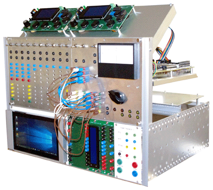
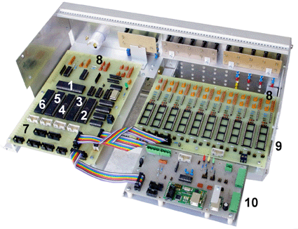
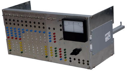
A computing device is to be built, which looks like a venerable analog computer, but is based completely on microcontrollers. 16 Atmel AVR microcontrollers emulate amplifiers, multipliers, function generators and the like. The device will be programmed by wire via a plug board. However, to select functions, set coefficients, display results and so on, a small computer is to be attached (despite being fond of old-fashioned technology, dials, multi-turn pots and the like would be too costly and would consume too much space). Each of the functional units has an attention key, whose actuation will cause the corresponding menu to appear on the screen. With appropriate microcontroller programs, the device could be made work, for example, as a digital or analog simulator or as a neural network.
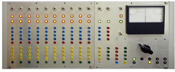
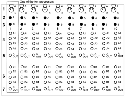
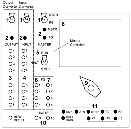
A closer look at the front panel of the “computing amplifiers”. Each AVR executes two computational functions (A, B). 1 – attention key; 2 – function A state indicator; 3 – function B state indicator; 4 – function A inputs; 5– function A outputs; 6 – function B inputs; 7 – function B outputs. A closer look at the front panel of the converters and the master controller. 1 – attention keys; 2 – state indicators; 3 – output converter inputs; 4 – input converter outputs; 5 – operation mode selector switch (RHR switch (Run - Halt - Reset)); 6 – function generator inputs; 7 – function generator outputs; 8 – moving-coil meter; 9 – selector switch; 10 – additional inputs; 11 – interfaces and power state indicators.
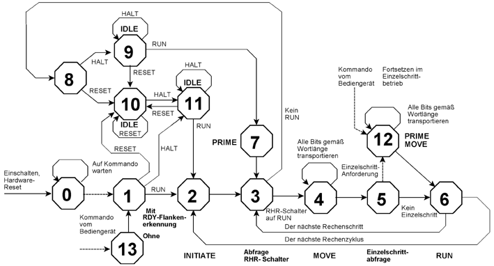
The master controller's state diagram:
|
|
|
|
June 20, 2016 Descriptions (in German*): Interfaces, principles of operation and commands: A closer look at the master controller's state diagram Drawings and descriptions (in German*):
*: Understanding should not that difficult. The signal identifiers are in English ... Some translations: Kommandogeraet = Master Controller Eingabewandler = Input Converter (converts analog input signals to the internal digital representation) Ausgabewandler = Output Converter (accepts digitally represented internal "signals" and converts them into analog or digital outputs to be shown on the built-in moving-coil meter or an oscilloscope, or sent to a personal computer). Rechengeraet = the ensemble of 10 microcontrollers programmed as "computational amplifiers" (Computational Subsystem). Zentraladapter = the board to attach the power supplies, the external interfaces and the programmer (Central Adapter). |
