 |
|
Projects: Microcontroller Modules
|
|
|
I State-of-the-art microcontrollers are essentially self-contained. Principally, they could be operated when held between two fingers or placed on the table while connected to power supply and peripheral devices via hookup wire (provided the wire is thin enough...). Hence it should not be that difficult to develop own microcontroller modules. By the way, the ultimate solution of a corresponding application problem would be the application-specific board with the microcontroller sitting somewhere in a corner. In this respect the module is only an interim solution. When developing own microcontroller modules, it is a matter of course to seek for opportunities to make improvements, to create something showing unique features. Our unique selling points can be summarized as follows:
To achieve these goals, we allow for a moderate increase in cost and dimensions - we build somewhat larger and use components, which are somewhat more expensive.
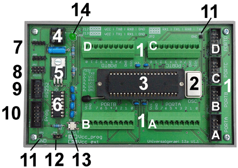
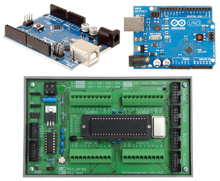
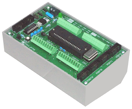
1) I/O connectors. Various types can be inserted. All I/O signals of the microcontroller are accessible (ports A, B, C, D). Depending on the connectors, other modules can be attached via cables or stacked. Here, a somewhat luxury type of terminal strips is shown. The application wiring ends in pluggable screw terminals. Hence the wires can be disconnected with little effort. 2) Clock Generator. A complete crystal clock generator can be inserted. This allows to operate the microcontroller up to its maximum clock frequency. 3) Microcontroller. The board can accommodate any Atmel ATmega microcontroller in a dual inline package with 40 pins, provided the power supply pins are in the center. It is possible to chose between different types; ranging from greatest simplicity (for example, ATmega16) up to a maximum number of features and memory capacity (for example, ATmega1284). Around the holes, enough space has been left to allow for insertion of a ZIF socket, thus enabling fastest processor swapping. 4) Power Supply. Power must be supplied from outside. The board has no voltage regulator. Convenient power sources are a 5-V or 3,3-V power supply unit, a 3,5 V or 4.8 V battery, or (via an appropriate external adapter) the USB. Power can be fed into the module via the terminal block or any other connector with VCC and GND pins. The other way round, all interface connectors with such pins can be used to power the attached circuitry. 5) Antireversal Protection. The venerable circuit invented by Bob Pease protects the module against polarity reversal. 6) RS-232 Signalization. There are microcontrollers with one UART or with two. The board supports up to two serial ports with RS-32 signalization. 7) Headers for RS-232 Connectors. When necessary, D-sub connectors are to be attached externally. This requires 3 pins (TX, RX and Ground). 8) RS-232 Configuration. The RS-232 signalization is activated by jumpers. 9) Header for serial 5 V signalization. This header is connected to the first UART. In the module family, there are two pin assignments, one for the slave or upstream connection and one for the master or downstream connection. This module is configured for slave attachment, downstream of a personal computer, a master controller, or a hub (active or passive). The Header comprises a VCC pin. It can be used to power external circuitry or to feed the module. Fig. 2 illustrates a typical example. Here the modules are fed via this header from the passive hub, which is in turn connected to a wall adapter. 10) SPI/Programmer Header. The board allows for inserting a header with 6 or 10 pins, respectively. The assignment of the 6 pins corresponds to that of the industry-standard Atmel programmers. The larger header provides two additional signals to support attachment of SPI devices like ethernet controllers, USB host controllers, or serial memories. If such a header is inserted, programmers are to be connected via a special adapter cable. 11) Ground Test Points. Two ground test points can be inserted to support oscilloscope attachment and the like. 12) Power Supply Jumper. This jumper is to be set to select the power source. 13) Reset Key. As experience shows, a reset key is an inexpensive, but convenient means to facilitate debugging and troubleshooting. 14) Power LED. choices how power can be fed (cf. pos. 4).
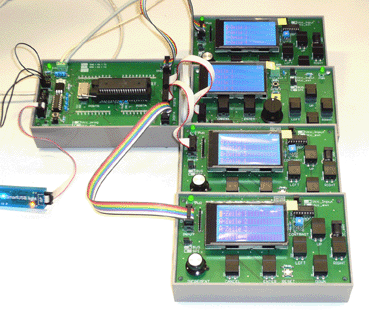
An experimental multiprocessor configuration. Five microcontroller modules are connected to a passive hub. One microcontroller is the master. Each of the controllers has its own I/O console, a human interface module 02/10.
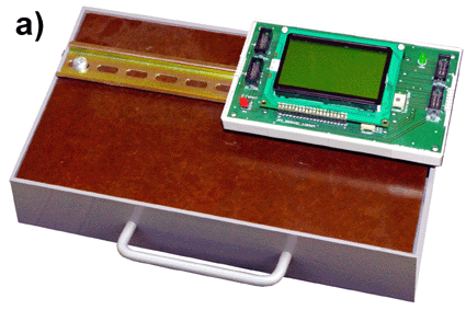
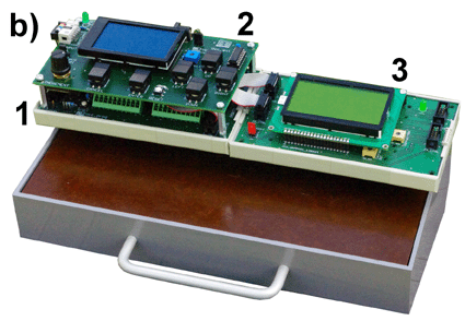
Modules mounted on a DIN rail. a) shows the mounting principle. b) is an educational system consisting of a microcontroller module (1), a human interface module (2) stacked above, and an LCD module (3), carrying a graphical LCD display.
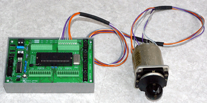
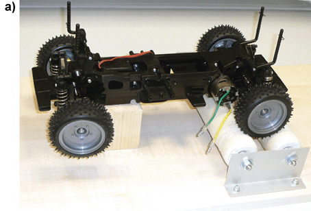
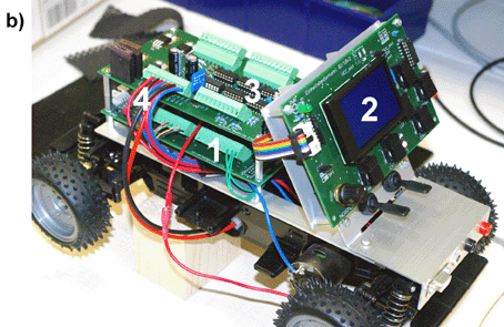
An educational model vehicle. a) shows the chassis on a makeshift test bench. b) illustrates, how our modules can be used as OEM building blocks. 1 - general purpose microcontroller module 12a. 2 - human interface module 02/10. 3 - an application-specific board. 4 - power wiring.
|
|
|
|
June 24, 2016 References have been updated. What makes the difference (apart from the size)?
Download a competitive analysis. |