|
|
|
Voltage-Level Translation in MCU Projects
|
|
|
Don't expect 24 V to be always 24 volts
The voltage range depends above all on the fluctuations of the grid voltage and the load regulation of the transformer. In industrial circuitry, special types of transformers are used, the so-called industrial control transformers, showing a load regulation of not more than 10% ([12]). Load regulation is the percent change in output voltage when the load goes from full load (VFL) to no load (VNL).
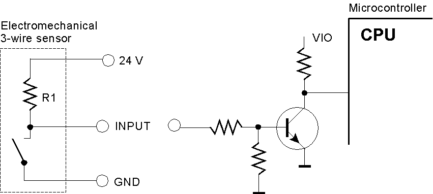
The voltage ratio of a typical control transformer is 0.2 for the 115-V grid and 0.1 for the 230-V grid, respectively. Principally, the output voltage equals input voltage times voltage ratio. The particular value, however, depends on the load. If the transformer is fully loaded, the output voltage corresponds to the root mean square (RMS). If the transformer runs idle, the output voltage is nearly equal to the peak voltage, being approximately VRMS times 1.4. The worst cases are (1) lowest grid voltage and full load and (2) highest grid voltage and no load. The admissible range of the grid voltage equals the nominal value ± 8.7% (105 to 125 V or 210 to 250 V, respectively). For example, full load corresponds to 105 V • 0.2, yielding 21 V; no load corresponds to 125 V • 0,2 • 1,1 (regulation) • 1,4 (peak value), yielding 38,5 V. IEC 61131-2 – the international standard Simple and IEC-compliant 24-V inputs This 3-wire sensor switches the input signal between 24 V (or somewhat below due to the voltage drop over R1) and 0 V. Only the signal level is to be translated. It can be done by a few discrete components.
An IEC-compliant sensor, however, always behaves as a current source. Current flows from the 24-V terminal through the sensor and the signal wire and the input circuitry of the translating device to ground.
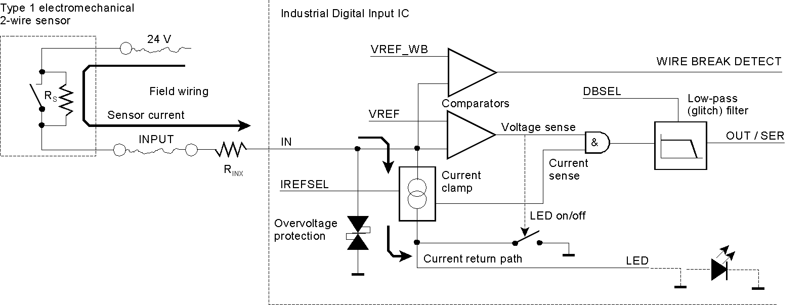
Here, some internals of the MAX22190 Octal Industrial Digital Input IC are shown ([22]). It can detect broken wires or shorts to ground. The sensor must source some current, even if in the OFF state. Hence the contact is paralleled by a resistor RS, ensuring a minimum current flow. So, no current at all will indicate a wire break fault condition.
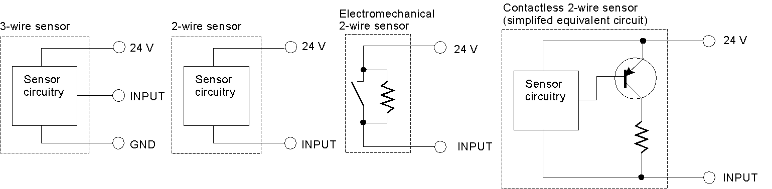
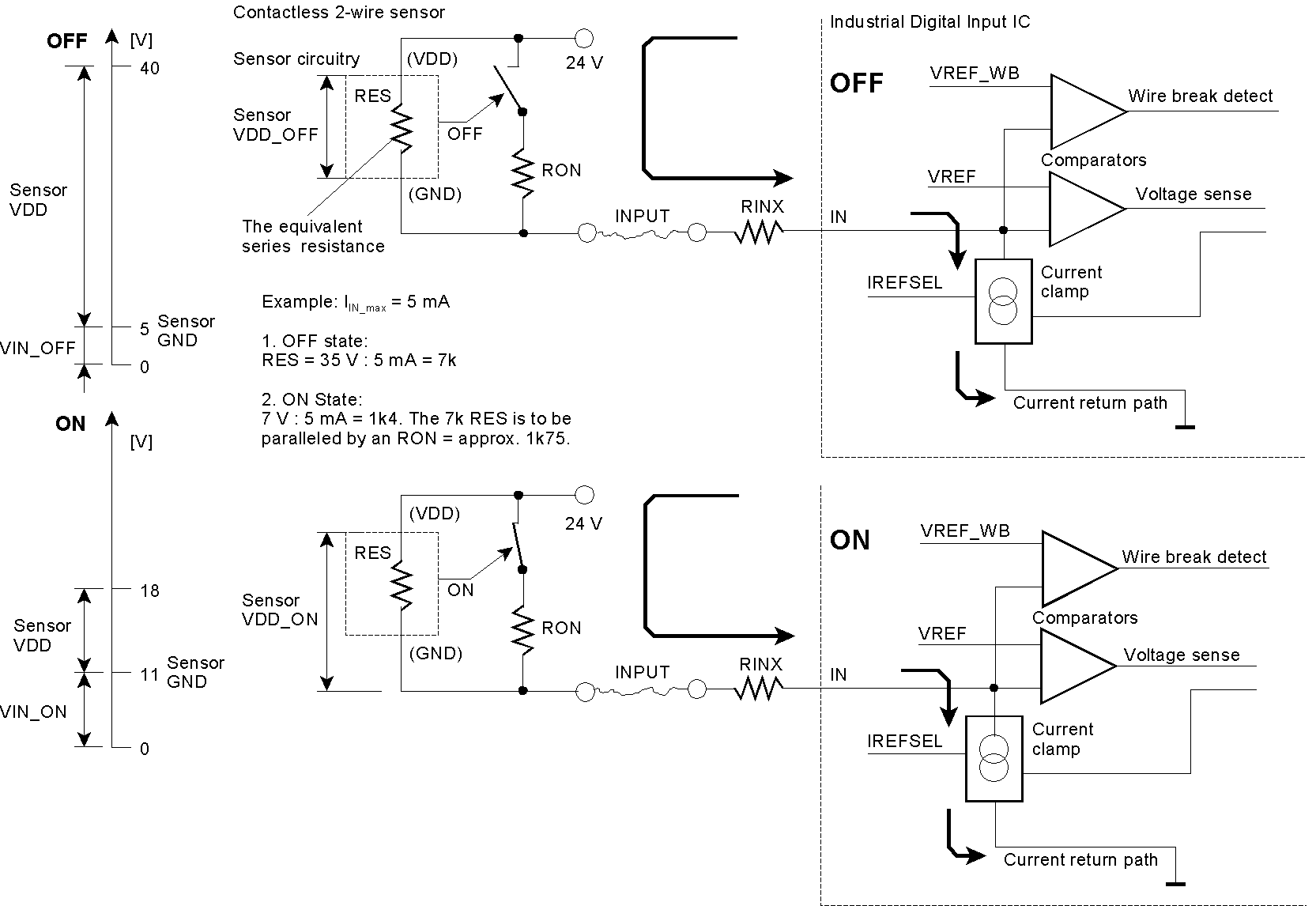
How to power the circuitry in a contactless 2-wire sensor (e.g., in a proximity switch)? Power is supplied by letting a current flow from the 24-V terminal via the input wire to ground. Therefore, the translation circuitry must behave as a current sink. In the OFF state, the signal must not rise above 5 V. In the ON state, it must be at 11 V or above. According to the IEC type, a current of up to 15 or even 30 mA may flow through the sensor. The sensor's circuitry may be seen as an equivalent series resistance causing a voltage drop because of the flowing current. This is the sensor's supply voltage (VDD).
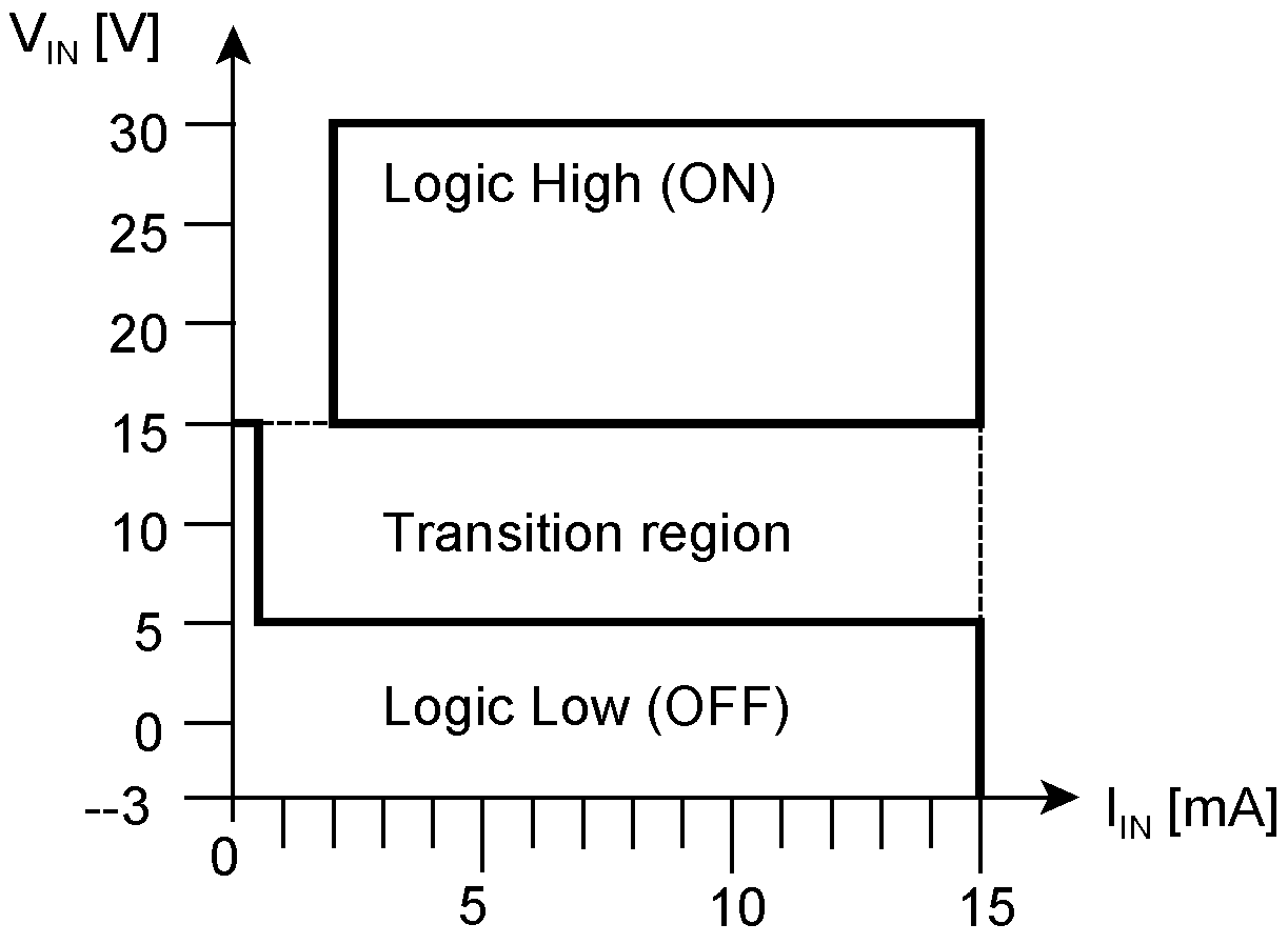
A simple worst-case analysis In the OFF state, the current flows only through the equivalent series resistance RES. The voltage drop must be large enough so that the voltage at the input terminal is well below the maximum VIN_OFF (VIL) voltage of 5 V (as stipulated in IEC61131-2). The worst case occurs if the sensor is fed with 40 V. Thus the voltage drop must become 35 V, yielding an RES = 35 V : 5 mA = 7 kOhm. In the ON state, the sensor's circuitry will activate an additional parallel resistance RP to decrease the voltage drop. It must be reduced so that the voltage at the input terminal is well above the minimum VIN_ON (VIH) voltage of 11 V (as stipulated in IEC61131-2). The worst case occurs if the sensor is fed with 18 V. To guarantee a voltage drop of not more than 7 V, the resistance of the sensor must be reduced to 7 V : 5 mA = 1.4 kOhm. To this end, the sensor must activate a parallel Resistor RP of approx. 1.75 kOhm. The sensor's circuitry must be content with an intensively varying power supply. In our example, the supply voltage (VDD) corresponds to the voltage drop varying between 7 and 35 V and the current may plummet down to somewhat around 2 mA. The power requirement of the sensor and the current-sinking capability of the translation device must fit together. For example, it will not work if the current clamp within the translation IC limits the input current to 2 mA while the sensor needs 5 mA. IEC 61131-2 sensor types and operating regions Type 1 operating regions. Type 1 concerns mechanical contacts and 3-wire sensors drawing a comparatively high quiescent current.
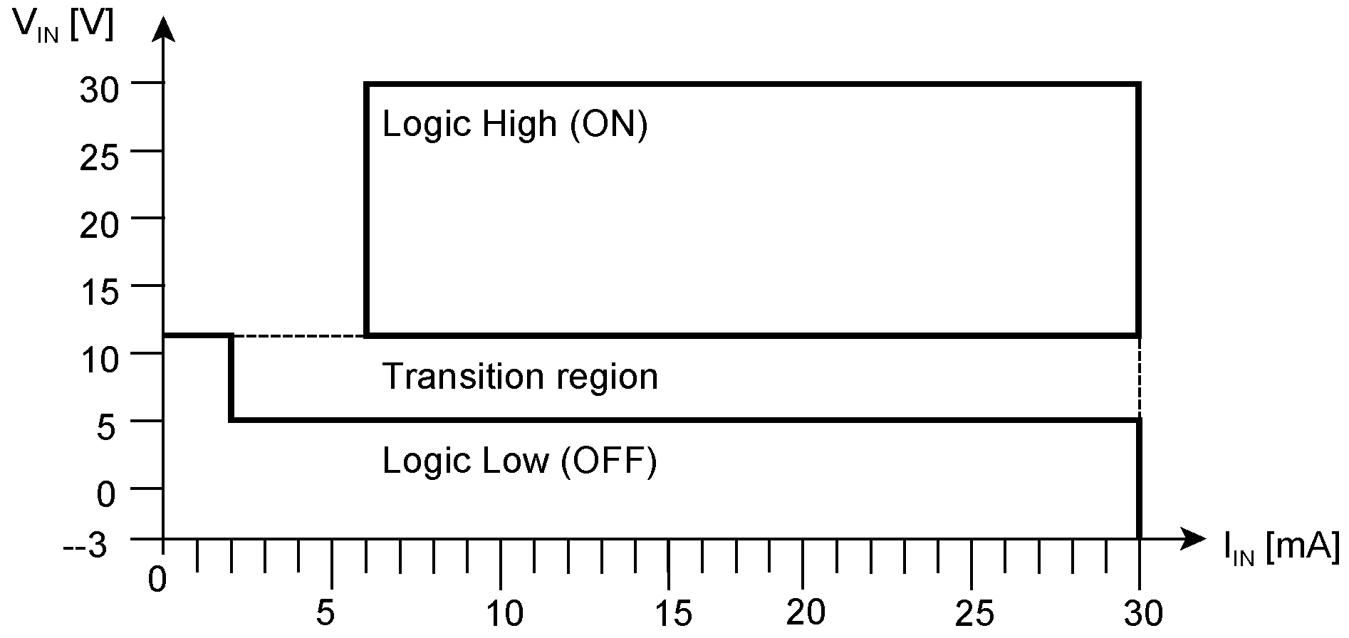
Type 2 operating regions. Type 2 relates to 2-wire sensors with a somewhat increased power consumption, for example, 2-wire proximity switches according to IEC 60947-5-2.
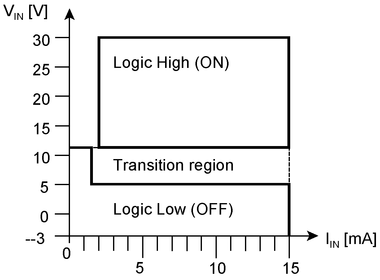
Type 3 operating regions. Type 3 has been defined to support 2- and 3-wire sensors with reduced power consumption.
|
|
|
|
24-V microcontrollers and CPLDs
|