|
|
|
Voltage-Level Translation in MCU Projects
|
|
|
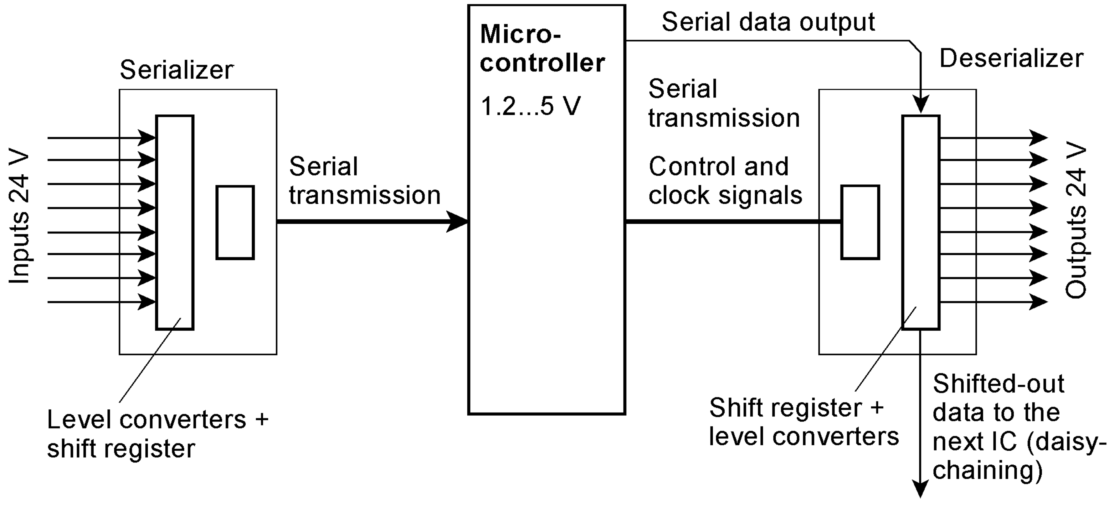
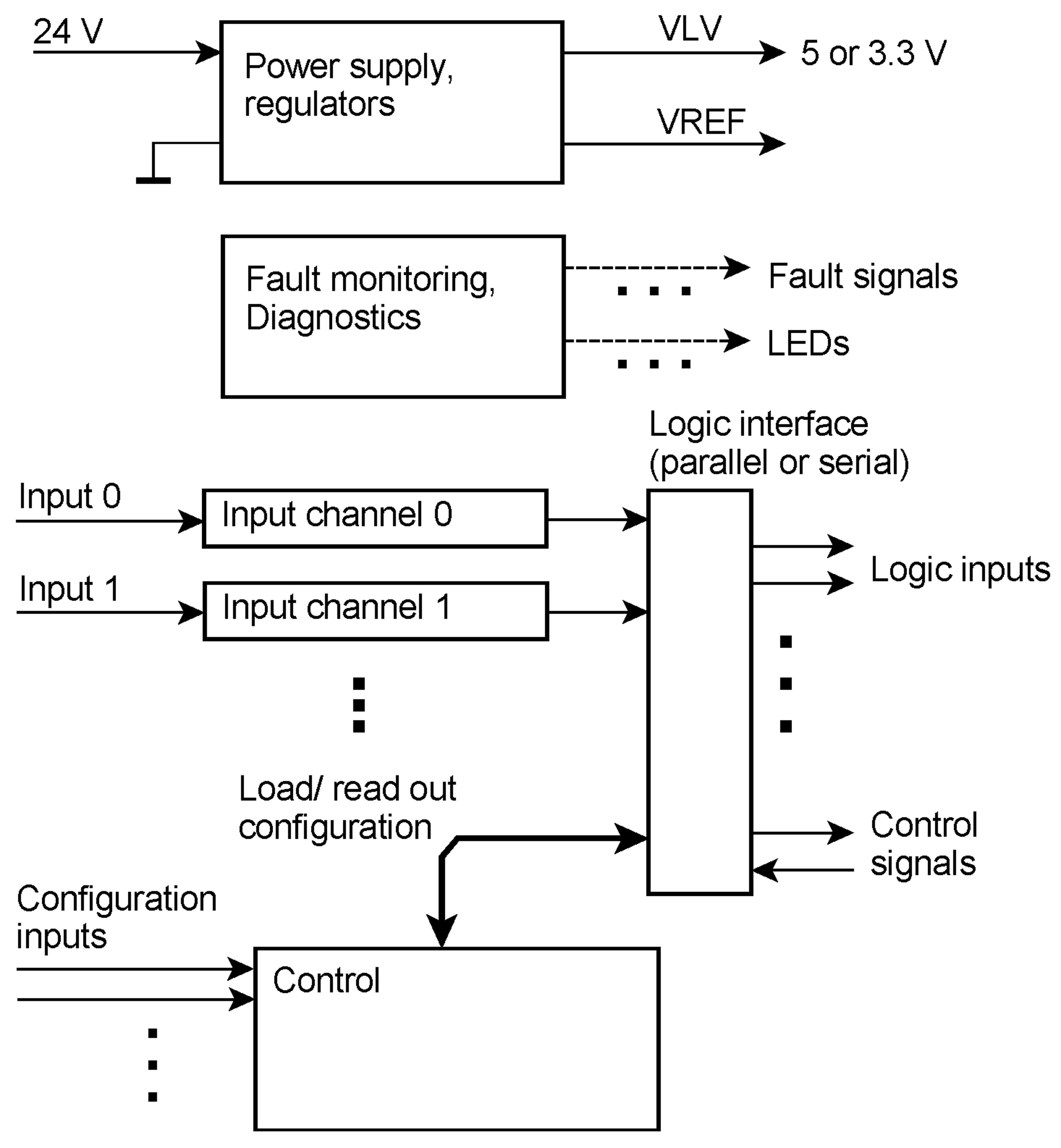
In the past, level translation problems were often solved by discrete components or small-scale (SSI) integrated circuits. Meanwhile, the magnitude and importance of the level-translation tasks have caused the semiconductor manufacturers to provide a broad portfolio of specific level-translation ICs. The differ mainly in the number of signals, the interface to the digital circuitry, ranges of signal levels and supply voltages, and which directions of signal flow they support. The logic interface Parallel interfaces have as much data signals at the logic side as at the 24-V side. They may be supplemented by control and status or fault-indicating signals. Typical serial interfaces adhere mostly to the SPI industry standard or are straightforward shift register interfaces. Those interfaces allow for daisy-chaining multiple level-conversion ICs. The serial interface is not confined to data transfer. It allows accessing configuration and diagnostic registers, too.
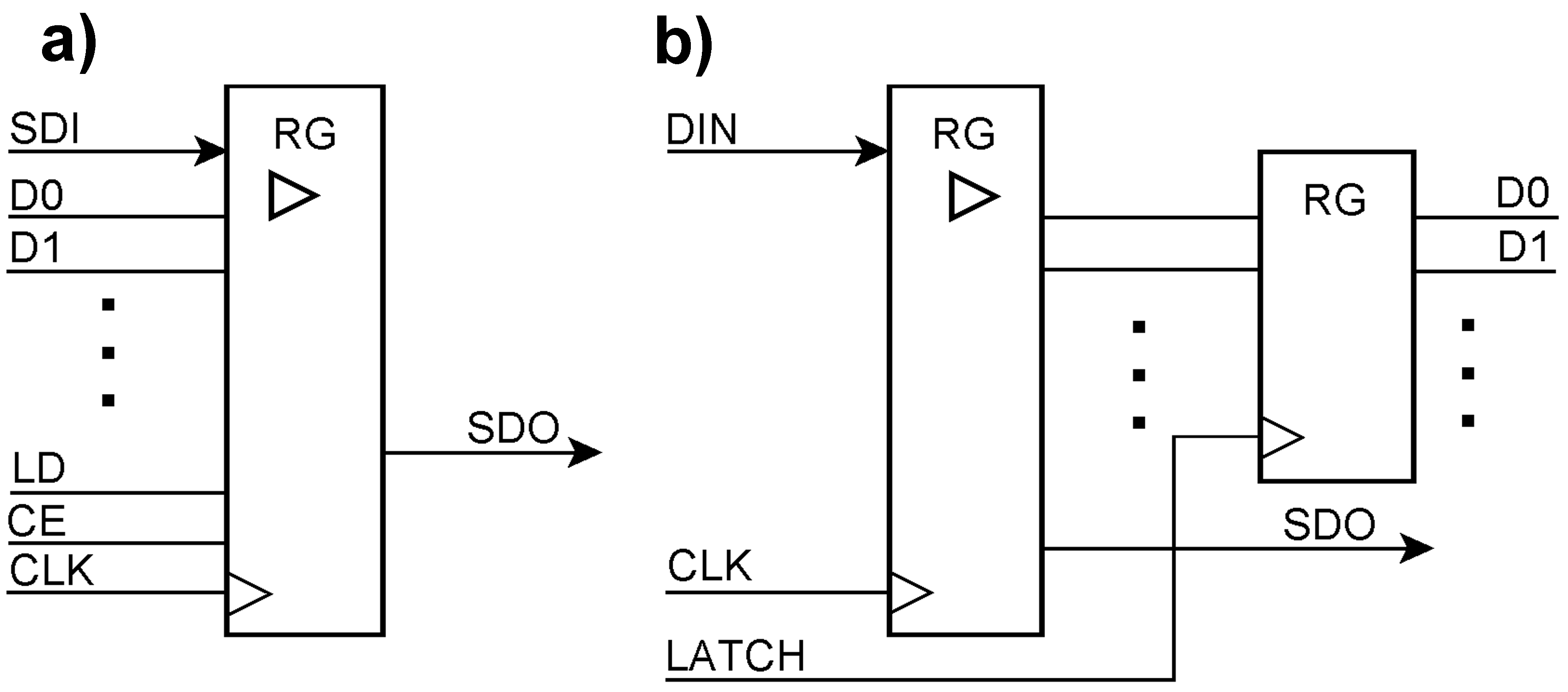
Typical serial interfaces adhere mostly to the SPI industry standard or are straightforward shift register interfaces. Straightforward shift register interfaces. a) shows an input serializer. An LD pulse clocks the parallel data into the shift register. Further clocks cause the register content to be shifted out bit by bit. The output deserializer (b) consists of a shift register with parallel outputs connected to a data register. Output data is shifted in. Then a latch pulse will cause the data to be transferred into the data register.
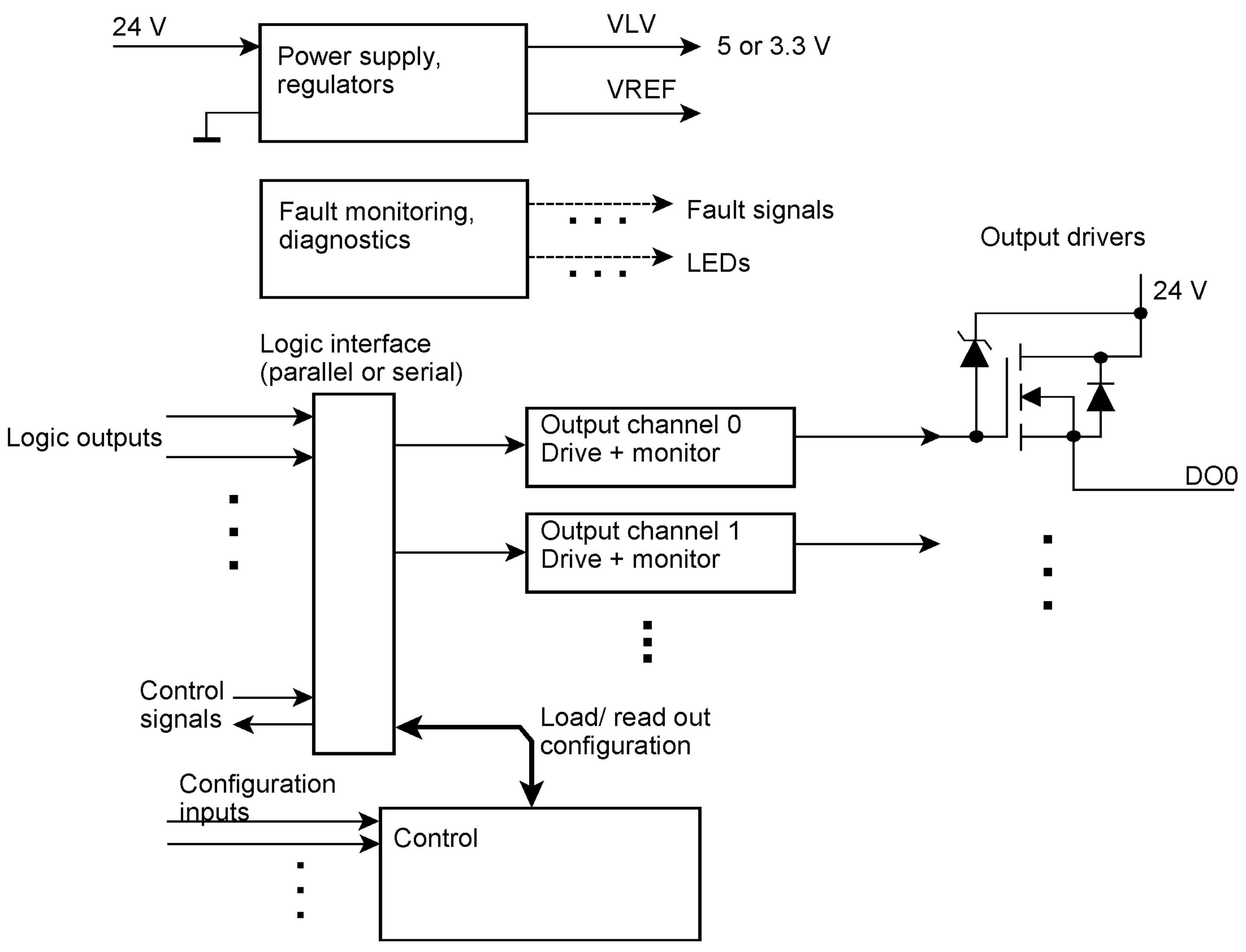
When developing a 24-V microcontroller, we may prefer serial interfaces to reduce the number of microcontroller pins required. On the other hand, when a CPLD is the core of our device, parallel interfaces may be better suited because serial interfaces need serializers, deserializers, and state machines to control them, thus eating up precious CPLD macrocells. 24-V Inputs A generic multi-channel input translator:
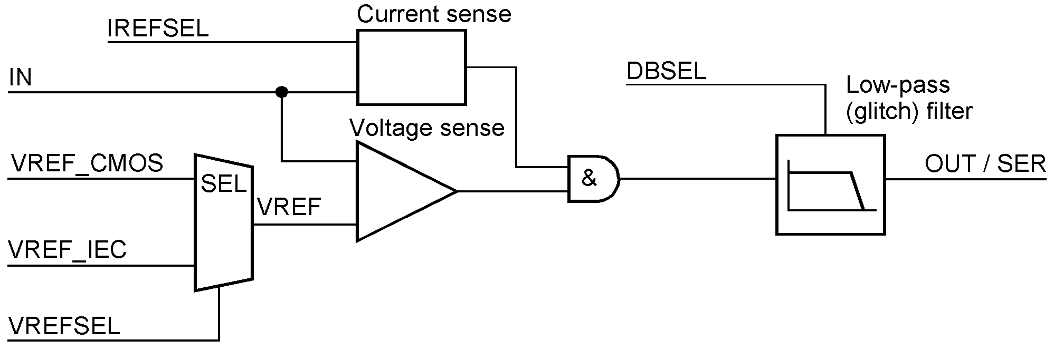
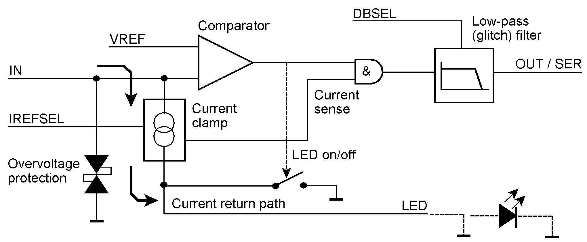
To detect to which region an input voltage corresponds requires comparing it with appropriate reference voltages. To be compliant with IEC 61131-2, however, the current must be evaluated, too. This is a very simplified illustration of the signal flow. The IREFSEL input is to be connected to an external resistor to set the current limit. VREFSEL is a logic input to select the voltage sensing trip point differentiating between OFF and ON. The trip point may be set to approximately 2.5 V (VREF_CMOS) or according to the IEC 61131-2 specification (VREV_IEC). Via the DBSEL inputs, the debouncing time may be selected (in an example between 0.025, 0.75, and 3 ms). Depending on the IC's interface, the logic signal representing the input is led directly to a pin (OUT) or the serializer part of the serial interface (SER).
The 24-V input is connected to current and voltage sensing circuitry. Both outputs are AND-ed together to deliver a logic input signal. In some ICs, this signal is run via a low-pass filter to eliminate glitches (debouncing). How the input current flows. If the input signal is in the OFF region, the LED switch will be closed. Thus the current will flow directly to ground. If the input signal is in the ON region, the switch is open, and the current will flow thru the LED. Thus LED current comes from the attached sensor, not from the level-translation IC (energyless LEDs).
How the input current flows. If the input signal is in the OFF region, the LED switch will be closed. Thus the current will flow directly to ground. If the input signal is in the ON region, the switch is open, and the current will flow thru the LED. Thus LED current comes from the attached sensor, not from the level-translation IC (energyless LEDs). 24-V Outputs A generic industrial driver/switch with high-side drive outputs:
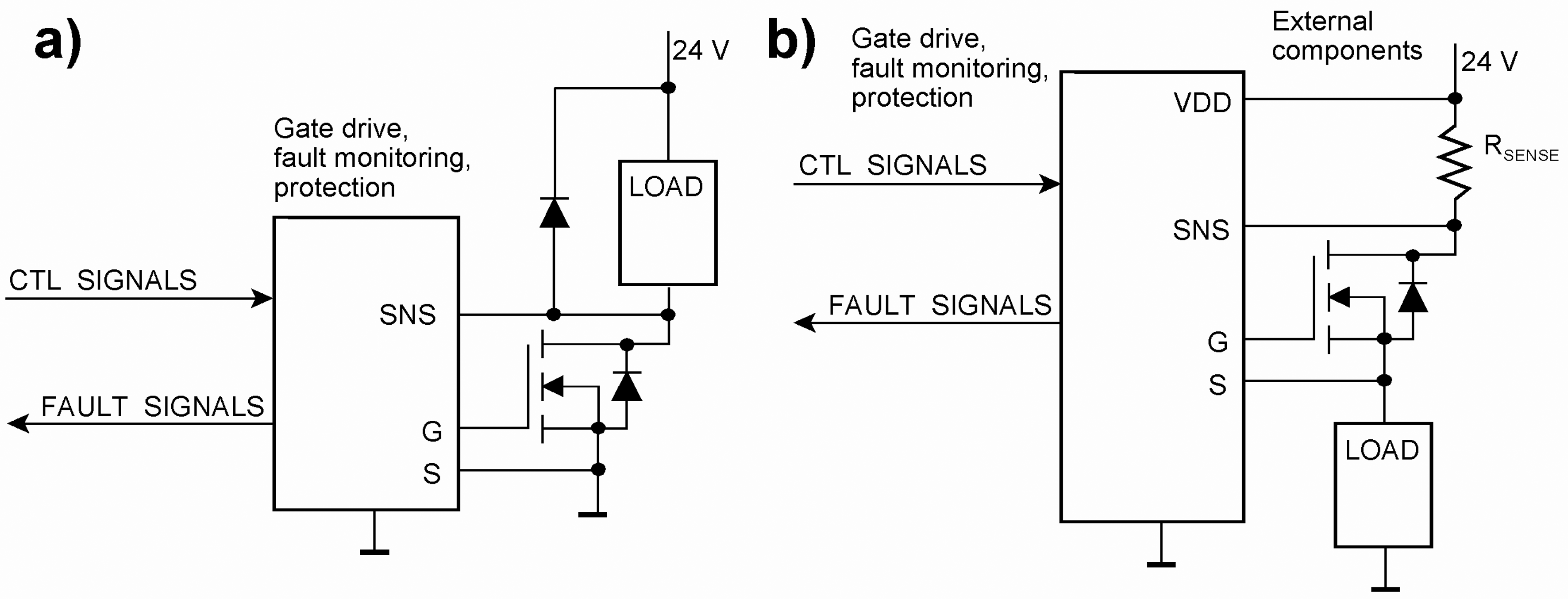
Comparatively straightforward output channels driving a low-side switch (a) or a high-side switch (b):
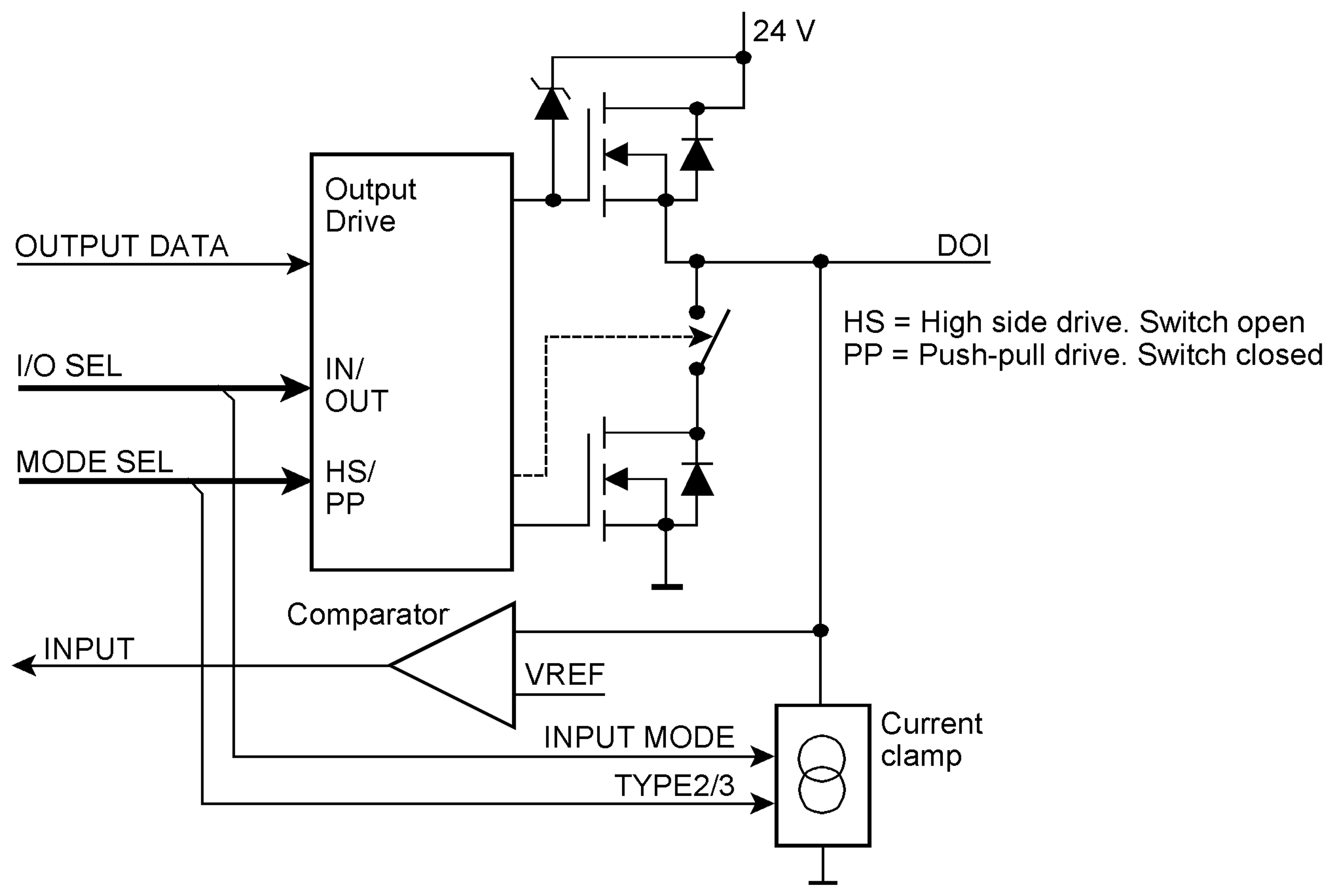
This channel allows the selection of various configurations: high-side, push-pull, high impedance (somewhat similar to the venerable tri-state drivers), or input modes according to one of the IEC 61131-2 types. The configuration is to be programmed via the logic interface.
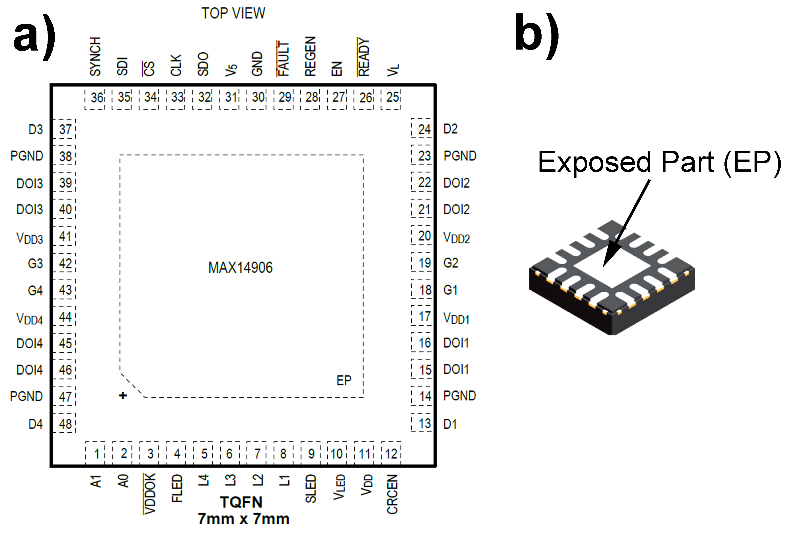
IC packages and PCB design Typical IC packages. a) shows the TQFN package of the MAX14906 Quad-Channnel Industrial Digital Output/Digital Input IC. It comprises four channels, as illustrated in Figure 16. TQFN = Thin Quad Flatpack, No leads. The dimensions are only 7 by 7 mm (approx. 0.28" by 0.28"). b) illustrates the principal appearance of such a package, shown from underneath.
|
|
|
|
24-V microcontrollers and CPLDs
|